
Steel Pipes for Mining Operations
An engineering reference for buyers of mining pipe — slurry and tailings mains, mine dewatering and process water, compressed-air and service lines, and the structural steel behind conveyors and headframes — with the grades, wear margins, linings and codes that keep a mine running.
Engineered Pipe for the Toughest Site on Earth
Slurry, water, air and structure — one supply contract, one mill.
Mines are some of the most demanding environments a steel pipe will ever see. Slurry lines carry ore concentrate and tailings at velocities that chew through wall thickness; process water and mine dewatering can be acidic enough to destroy uncoated carbon steel in months; compressed-air and service lines must hold pressure at altitude and in freezing winters; and every conveyor trestle, headframe and equipment frame is a structural job in its own right.
CREATEEL supplies the full welded-pipe catalogue for all four service groups from one mill — API 5L line pipe for slurry and water, AWWA C200 water pipe, ASTM A53 / A106 and EN 10217 for air and pressure, and ASTM A500 / EN 10219 hollow sections for structures — with the wear margins, linings and mill certifications a mining specification calls for.
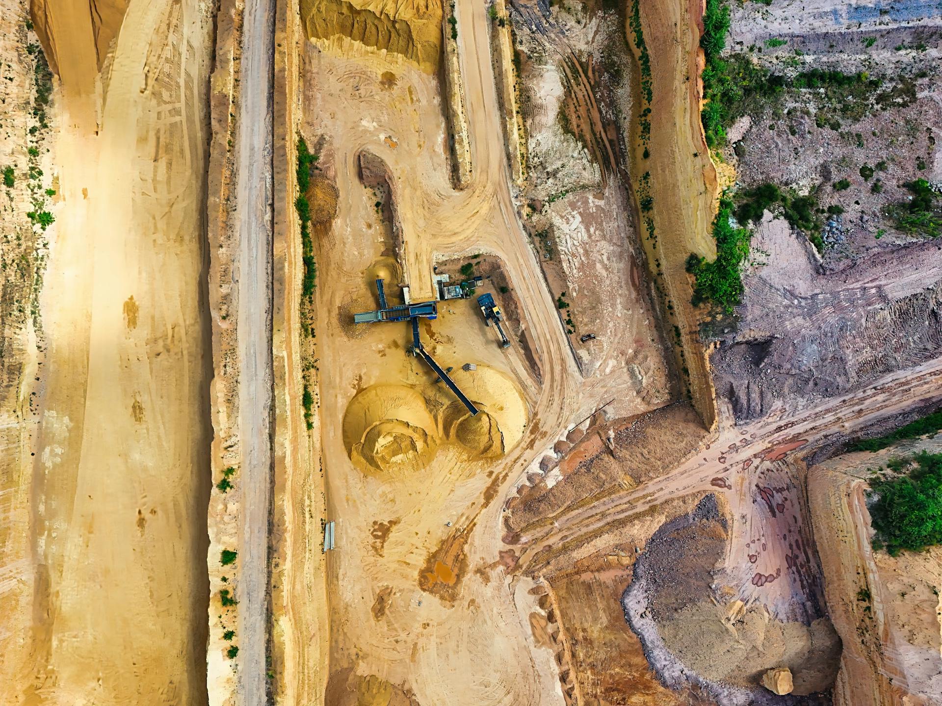
Mineral-processing plant: slurry, water and utility piping on a single site.
Four Loads That Decide a Mining Pipe Spec
Wear, chemistry, pressure and climate — in that order.
Four physical loads decide every mining-pipe spec. Get any one wrong and the line fails early — so the rest of this page walks through how grade, wall, lining and code answer each one.
Abrasion
Slurry and tailings carry hard particles at 1.5–3.0 m/s. Wall loss follows the particle size, concentration and velocity — and it rises exponentially with speed.
- Key specifications
- • Wear rate ∝ v²
- • Coarse particles > fine
- • Elbows wear fastest
Corrosion / pH
Acid mine drainage (pH 3–4) can destroy uncoated carbon steel in 12–18 months. External soil and salty backfill add a second attack path.
- Key specifications
- • pH < 5 = aggressive
- • Sulfides & chlorides
- • Needs lining or alloy
Pressure / depth
Dewatering shafts below 250 m work at 18–25 bar; surface mains add surge. Wall must cover pressure plus a sacrificial wear margin.
- Key specifications
- • Up to 25 bar dewatering
- • Surge + transient
- • t = PD/2SE + margin
Altitude / cold
High-altitude and Arctic mines need low-temperature toughness. Standard carbon steel goes brittle below -20 °C without the right grade.
- Key specifications
- • A333 Gr.6 to -45 °C
- • Charpy 18 J avg @ -45 °C
- • Arctic design factor
Four Service Groups on Every Mine Site
Slurry, water, air and structure — one supplier covers all.
From a gold-mine dewatering shaft to an iron-ore tailings line to a copper concentrator, the same four families appear — each pushing a different parameter to the front.
Where each pipe family fits
Click through to the detail cards below
Slurry & tailings
Pumped transport of ore concentrate and waste. High solids, high wear, long distances — the most engineered line on the site.
- Key specifications
- • API 5L X52–X70 PSL1 / PSL2
- • Heavy-wall LSAW
- • Lined or AR steel
Water & dewatering
Process water, mine dewatering and camp potable supply. Pressure-rated, lined, corrosion-safe.
- Key specifications
- • AWWA C200
- • Cement / FBE lined
- • Up to 25 bar
Air & services
Compressed-air mains, vent lines and plant utility piping. Leak-tight, galvanized for moisture.
- Key specifications
- • API 5L / A53
- • Galvanized
- • Tested 1.5× pressure
Site & structural
Conveyor trestles, headframes, equipment and building frames. Hollow sections, bolted or welded.
- Key specifications
- • ASTM A500 / A1085
- • EN 10219 / 10210
- • Bolted or welded
Slurry & Tailings Pipelines
Hold velocity above deposit, wall above wear — line for 20-year life.
Slurry and tailings pipelines are hydro-transport lines: ore or waste suspended in water, pumped over kilometres. The design target is to stay above the deposit velocity (typically 1.0–1.7 m/s) so solids never settle, while keeping velocity low enough that wear stays economical — because wall loss scales roughly with the square of velocity. Wall thickness is pressure wall plus a sacrificial wear allowance, and the pipe is usually lined (cement mortar, rubber, HDPE or ceramic) or made from abrasion-resistant steel (AR400 / AR500).
Real reference: a gold-mine tailings line ran DN650 (OD 660 mm) API 5L Grade B at a 0.60 design factor (max 4160 kPa), with a 12 mm HDPE liner sized for a 20-year campaign at ~0.46 mm/yr of measured liner wear (about 9 mm consumed over the campaign, leaving a safety margin). For abrasive duty, LSAW is preferred over spiral — the straight seam gives a smoother inner surface and more uniform wear.
Slurry pipeline design drivers
Per ASME B31.4 — liquids and slurries (B31.11 withdrawn)
| Parameter | Typical mining range | Why it matters |
|---|---|---|
| Solids concentration | 45–65% w/w | Sets density, head loss and pump duty |
| Velocity | 1.5–3.0 m/s | Below deposit = settling; above = fast wear |
| Wear allowance | 6–15 mm (up to 25 mm) | Sacrificial wall; life = margin / wear rate |
| Preferred process | Heavy-wall LSAW / AR steel | Smooth seam, uniform wear, thick wall |
| Lining | Cement / rubber / HDPE / ceramic | Extends life 3–5× vs bare steel |
Water & Dewatering Systems
AWWA C200 steel pipe, internally lined, externally coated.
Mine dewatering and process-water lines are built to the water-pipe rulebook, not the oilfield one. AWWA C200 governs steel water pipe 6 in and larger (referencing ASTM A139, A252, A53 and API 5L), with design per AWWA M11. The pipe is lined internally — cement mortar (AWWA C205) for raw and neutral water, fusion-bonded epoxy (AWWA C213, NSF/ANSI 61 for potable) or liquid epoxy (AWWA C210) for acidic or demineralized water — and coated externally with FBE or 3PE when buried. Dewatering shafts can reach 18–25 bar, so wall is pressure-plus-wear, exactly like a slurry line.
Water & dewatering pipe stack
AWWA C200 + C205/C210/C213 + M11
| Service | Standard | Internal protection |
|---|---|---|
| Raw / process water | AWWA C200 | Cement mortar (C205), 6–13 mm by OD |
| Potable / treated | AWWA C200 + NSF 61 | FBE (C213) or liquid epoxy (C210) |
| Dewatering shaft | API 5L / AWWA C200 | Cement lining + 3PE external |
| Fire water | ASTM A795 (NFPA) | Galvanized or coated |
| Buried main | AWWA C200 | FBE 300–450 µm / 3PE 2.5–4.0 mm |
Steel Grades for Mining Pipe
X-grades for flow, A500 for frames, A333 for the cold.
For slurry and water mains the grade is almost always an API 5L X-grade — X52 is the mining workhorse, stepping up to X65 / X70 for long, high-pressure lines. Structural frames use ASTM A500 / EN 10219. For Arctic or high-altitude mines, A333 Gr.6 carries mandatory low-temperature toughness down to -45 °C.
Grade selection table
API 5L PSL1 / PSL2 · ASTM A53/A106/A500/A333 · EN 10217
| Grade | Fy min (MPa) | Typical use in mining |
|---|---|---|
| API 5L X42 | 290 | Lower-pressure slurry & water mains |
| API 5L X52 | 360 | Slurry, tailings, dewatering (most common) |
| API 5L X60 | 415 | Higher-pressure long-distance slurry |
| API 5L X65 | 450 | Large-diameter high-pressure mains |
| API 5L X70 | 485 | Heavy-wall, highest-strength slurry lines |
| ASTM A53 Gr.B | 240 | General / service / low-pressure water |
| ASTM A106 Gr.B | 240 | High-pressure (>250 psi) water & steam |
| ASTM A500 Gr.C | 345 | Conveyor / headframe / equipment frames |
| ASTM A333 Gr.6 | 240 | Low-temperature (to -45 °C) dewatering |
| EN 10217-1 P235/P265 | 235 / 265 | European welded pressure pipe |
Manufacturing Routes & Diameter Coverage
Four processes, one mine — pick by diameter and wall.
Four processes cover the whole mining range. Seamless is the choice where a weld seam is unwelcome (high-pressure shafts, acid water); ERW covers distribution and structural HSS; LSAW gives the heavy-wall, smooth-seam mains that slurry likes; spiral welding reaches the largest diameters at the lowest cost.
Process comparison
Match the process to diameter, wall and seam-smoothness need
| Process | Typical OD | Mining use |
|---|---|---|
| Seamless (SMLS) | 10 – 610 mm | High-pressure shafts, corrosive water, no weld seam |
| ERW / HFW | 20 – 600 mm | Distribution, air lines, structural HSS |
| LSAW (UOE/JCOE) | 400 – 1600 mm | Large slurry mains, heavy-wall, smooth seam |
| SSAW (spiral) | 219 – 3048 mm | Very large diameter water & slurry — economical |
Wall Thickness & Wear Allowance
Pressure wall + corrosion + wear — the mining margin.
Wall thickness is the single most important mining-pipe decision. Start from the pressure wall t = (P × D) / (2 × S × E), then add a corrosion allowance (3–6 mm on standard water lines) and a larger wear allowance for slurry — typically 6–15 mm on abrasive duty, up to 25 mm on heavy-wall LSAW. Because wear rises with the square of velocity, holding velocity just above deposit speed is worth more than adding wall. A real South-African gold-mine dewatering line (18 bar, pH 3.5) ran API 5L X52 ERW at 8 mm wall (the 18 bar pressure requirement is only about 2 mm at ERW diameters — the balance of the wall is the corrosion and wear allowance) with 3PE outside and a 5 mm liquid-epoxy lining (AWWA C210) inside — specified instead of cement mortar because the water sits at pH 3.5 — and it has run 12+ years maintenance-free.
Wall-thickness guide
Per ASME B31.4 / AWWA M11 practice
| Service | Wall / allowance | Life driver |
|---|---|---|
| Standard water | 3–6 mm allowance | Corrosion only |
| Slurry transport | 6–10 mm allowance | Sliding + impact wear |
| Abrasive slurry | 10–15 mm wall | Coarse-particle impact |
| Heavy-wall LSAW | up to 25 mm | Maximum sacrificial margin |
| Pump suction | ≥ 8 mm minimum | Avoid cavitation erosion |
Linings & Coatings for Abrasion and Chemistry
Line the inside for wear, coat the outside for soil.
Internal lining is what turns a steel pipe into a 20-year mining asset. Cement mortar (AWWA C205, 3–6 mm) is the workhorse for slurry, tailings and neutral water — it is cheap, abrasion resistant and raises the pH at the wall. Rubber (3–12 mm) and HDPE slip-liners handle the most abrasive or acidic duties; FBE and liquid epoxy (AWWA C213 / C210) give a smooth, chemically resistant surface and are NSF-61 certified for potable water. Externally, FBE or 3PE protects buried pipe from soil and groundwater attack.
Selection by duty
Match thickness and standard to the service
| Lining / coating | Thickness | Best for |
|---|---|---|
| Cement mortar (C205) | 6–13 mm (by OD) | Slurry, tailings, neutral water |
| Rubber | 3–12 mm | High-abrasion, acidic slurry |
| HDPE slip-liner | 6–24 mm | Very long life, low friction |
| FBE (C213) | 300–450 µm | Buried, potable (NSF 61) |
| 3PE (ISO 21809-1) | 2.5–4.0 mm | Rocky soil, aggressive ground |
| Galvanizing (EN ISO 1461) | 85–100 µm | Above-ground air / service lines |
Corrosion, Acid Water & Low-Temperature Service
Below pH 5, line it or alloy it — and mind the cold.
Acid mine drainage is the fastest way to lose a pipe. Below pH 5, uncoated carbon steel can fail in 12–18 months; a sulfur mine at pH 3–4 saw ordinary pipe gone in under two years. The fixes are lining (cement / rubber / FBE), 3PE external coating, or stepping up to alloy — 316L for chlorides, duplex 2205 for aggressive leach. For cold sites, the metal itself must be tough: A333 Gr.6 is qualified to -45 °C (a Mongolian coal mine at -40 °C ran a full winter with zero failures), while standard carbon steel goes brittle without it. Where H2S is present, specify NACE MR0175 / ISO 15156 sour-service limits.
Material by corrosive condition
pH, chlorides and H2S set the choice
| Condition | Recommended material | Standard |
|---|---|---|
| pH 5–7, mild | Carbon steel + cement / FBE lining | AWWA C205 / C213 |
| pH < 5, sulfides | 316L / duplex 2205 stainless | ASTM A312 / A790 |
| Chloride / brine | 316L or duplex | NACE MR0175 where H2S |
| Arctic / high altitude | A333 Gr.6 low-temperature | ASTM A333 (≥ -45 °C) |
| Sour (H2S) service | Controlled-hardness steel | NACE MR0175 / ISO 15156 |
External protection
Buried pipe needs a continuous barrier
- • FBE 300–450 µm — standard soil
- • 3PE 2.5–4.0 mm — rocky / corrosive soil
- • Coal-tar epoxy — wastewater, aggressive
- • Holiday-tested, no bare steel in ground
Slurry Hydraulics & Wear-Rate Design
Velocity sets both the settling risk and the wear rate — design the window, then size the wall.
Two failure modes decide a slurry line’s life, and both are governed by the same variable. Run too slow and the solids drop out of suspension, building a sliding bed that wears the bottom of the pipe; run too fast and erosion climbs steeply — for sliding abrasion, wall loss scales with roughly the square of velocity, and for coarse angular particles it rises faster still. The design target is therefore a narrow band: comfortably above the critical deposition velocity for the coarsest particle fraction, and no higher than the head-loss and wear budget allows. Wall is then sized from the wear model rather than from pressure alone — on most mining duties the pressure requirement is the smaller number. Fix the band with a pilot loop or plant data before you buy the pumps, and verify the model afterwards with periodic ultrasonic wall-thickness surveys at the first bend.
Hydraulic design window
Planning ranges — confirm the band with a pilot loop or plant data
| Parameter | Planning range | Design basis |
|---|---|---|
| Critical deposition velocity (Vc) | 1.0–1.7 m/s | Rises with particle size, solids concentration and pipe diameter; Durand-type correlations, then verify on site |
| Operating velocity | 1.5–3.0 m/s | Hold at 1.1–1.3 × Vc so no stationary bed forms at the low end |
| Solids concentration | 45–65 % w/w | Sets slurry specific gravity (typically 1.2–1.7), which drives head loss and pump duty |
| Wear velocity exponent (n) | ~2 sliding abrasion; 2.5–3+ coarse impact | Wear rises with velocity to the power n — doubling v roughly quadruples wall loss at n = 2 |
| Head loss | 0.02–0.08 m per m of pipe | Darcy–Weisbach with a slurry-adjusted friction factor; check it against pilot-loop data |
| Pump duty | P = ρ · g · Q · H / η | Size for the densest slurry and the highest solids load, not for the annual average |
Wear rate and lining life
Planning ranges for abrasive slurry — verify with wall-thickness surveys
| Material / lining | Planning wear rate | Remarks |
|---|---|---|
| Bare carbon steel | 0.2–1.5 mm/yr | Strongly velocity- and particle-dependent; never acceptable alone on coarse slurry |
| Cement mortar (AWWA C205) | 0.05–0.5 mm/yr | 6–13 mm by diameter; also raises the pH at the wall |
| Rubber lining (3–12 mm) | 0.05–0.5 mm/yr | Best on coarse angular solids at moderate velocity |
| HDPE slip-liner | ~0.3–0.5 mm/yr | Low friction; the DN650 tailings case above measured 0.46 mm/yr |
| Ceramic (alumina tile) | below 0.05 mm/yr | Highest capex, lowest wear per tonne — long-distance and high-pressure duties |
| AR400 / AR500 steel | 0.1–0.6 mm/yr | For bends, chutes and troughs rather than whole lines |
Wear life = usable thickness ÷ average wear rate. Size from the worst-case bend, never from the straight-run average, and confirm the model with ultrasonic surveys at the first bend after commissioning.
A Six-Step Specification Guide
From service to test certificate — the spec the mill needs.
Define the service
Slurry, water, air or structure — and the worst case: particle size, concentration, pH, pressure, altitude.
Pick the grade
API 5L X52 for most slurry/water; X65/X70 for long high-pressure; A500 for frames; A333 Gr.6 for the cold.
Set wall & wear
Pressure wall t = PD/2SE, then +3–6 mm corrosion and +6–15 mm (up to 25) wear allowance.
Choose process & OD
Seamless for shafts, ERW for distribution, LSAW for heavy slurry mains, SSAW for large diameters.
Specify lining & coat
Cement/FBE inside, FBE/3PE outside; rubber or HDPE for extreme abrasion; 316L for acid.
Confirm codes & test
ASME B31.4 (liquids and slurries) or AWWA C200/M11; weld per AWS D1.1; NDT, hydro test to the governing code, MTC per EN 10204.
Bends and Elbows for Slurry Service
Slurry rarely wears pipe out in the straights — it wears out bends, where particles slam the outer radius and the flow separates. Bend strategy is therefore the single biggest lever on pipeline life-cycle cost.
| Option | Wear resistance | Cost profile | Best for |
|---|---|---|---|
| Thick-wall steel bends (sacrificial wear allowance) | Moderate — steel is the consumable | Lowest capex, predictable replacement cycles | Slow-moving, low-abrasivity slurries |
| Rubber-lined bends | High for coarse, angular particles at moderate velocity | Mid capex; heavier sections | Mine discharge lines with coarse solids |
| Ceramic-lined bends (alumina tile / composite) | Highest for fine, high-velocity abrasive slurry | Highest capex; lightest wear per tonne | Long-distance tailings and high-pressure duties |
| Hot induction bends (3D–6D) | Gradual radius limits flow separation vs tight elbows | Per-bend pricing; keeps grade and wall matched | Direction changes where a smooth bore matters |
Note: Long-radius routing beats frequent tight elbows: every direction change multiplies local wear several-fold relative to straight pipe, so the cheapest meter of pipeline is often the one you never needed to bend.
Quality Assurance: What We Test, and Why
Every line on the MTC ties back to a clause in the spec.
Dimensional & wall
OD ±1%, wall ±10% (or per AWWA C200), straightness ≤0.2% L
- Key specifications
- • API 5L §9 / AWWA C200 / EN 10217
Chemical analysis
Heat & product analysis: C, Mn, S, P, CEV where specified
- Key specifications
- • API 5L §8 / ASTM A751
Tensile & yield
Yield, tensile, elongation on transverse specimens
- Key specifications
- • API 5L §7 / ASTM A370 / EN ISO 6892-1
Charpy impact
27 J min average at 0 to -20 °C per API 5L PSL2 (grade- and wall-dependent); A333 Gr.6: 18 J average / 14 J single at -45 °C
- Key specifications
- • API 5L / ASTM A370 / A333
Weld-seam NDT
100% UT or RT on ERW/LSAW/SSAW seam, agreed acceptance
- Key specifications
- • API 5L §10 / EN ISO 17640 / AWS D1.1
Hydrostatic test
1.25× (ASME B31.4) to 1.5× (ASME B31.3) design pressure, held per spec
- Key specifications
- • API 5L §11 / AWWA C200
Lining / coating
Coating thickness, adhesion & holiday detection; cement mortar ±
- Key specifications
- • AWWA C205/C213 / ISO 21809 / EN ISO 1461
MTC & marking
Heat number, grade, size, standard stamp, EN 10204 3.1 cert
- Key specifications
- • EN 10204 / API 5L §15
Welding, Field Joints & Commissioning
The mill certifies the pipe — the field decides whether the line lasts.
Mill-seam quality is covered by the product standard and by the mill test certificate; everything that happens after the pipe leaves the yard is covered by the construction code, and that is where mining lines most often fail early. On an abrasive duty an internal weld bead or a misaligned root becomes a wear pocket, and one unbonded field joint is a corrosion cell waiting for the first wet season. Insist on a qualified welding procedure and qualified welders, a stated NDT acceptance level on every girth weld, field-joint coating compatible with the shop coating, and a hydrostatic test you have witnessed or at least reviewed. Before hand-over, prove the bore with a gauge pig and take the as-built records — weld map, NDT reports and heat numbers traceable to the mill certificate.
Field execution and acceptance
Typical requirements — the governing construction code always takes precedence
| Activity | Typical requirement | Reference |
|---|---|---|
| Welding procedure (WPS / PQR) | Qualified for the process and positions used; impact-tested where the design temperature falls below 0 °C; preheat around 150–200 °C for heavy wall and high CEV | ASME IX / AWS D1.1 / EN 1011-2 |
| Welder qualification | Each welder qualified for the position and process actually used on site, records kept | ASME IX QW-300 / AWS D1.1 |
| Girth-weld NDT | 100 % visual; RT or UT on girth welds to an agreed acceptance level; AUT where the specification calls for it | ASME B31.4 Ch. VI / AWS D1.1 / EN ISO 17640 |
| Field-joint coating | Heat-shrink sleeve or compatible FBE / liquid epoxy, holiday-tested before and after backfill | ISO 21809-3 / EN ISO 21809 |
| Lined-pipe field joints | Lining hold-back at the pipe ends, then field-lining with fast-setting mortar or epoxy — no bare steel left in the bore | AWWA C205 / AWWA C602 |
| Hydrostatic test | 1.25 × design pressure per ASME B31.4 (1.5 × per ASME B31.3), held for the code duration after stabilisation | ASME B31.4 Ch. VI / ASME B31.3 Ch. VI |
| Cleaning & gauge pigging | Flush, then run a gauge pig to prove the minimum bore; clear weld spatter and construction debris before first slurry | Project commissioning plan |
| Records hand-over | Weld map, NDT and test reports, coating records, and heat numbers traceable to the mill certificate | EN 10204 / project QA plan |
Field rule: every flange is a wear pocket and a leak path — weld the line, and keep girth welds out of the bends wherever the routing allows it.
Standards & Certification Map
A complete mining-pipe specification is a stack of standards — from the product spec through grade, lining, welding, design code and documentation. The five columns below are the ones our mill & engineering team reach for first; project-specific clauses (sour service, arctic, seismic) are added on top.
Pipeline product
- API 5L (PSL1 / PSL2) — Line pipe for slurry & water mains, X42–X70
- ISO 3183 — International equivalent of API 5L
- ASTM A139 — EFW steel pipe for water service
- EN 10217-1 — Welded steel tubes for pressure purposes
- GB/T 9711 — Chinese line-pipe standard (API 5L equivalent)
Water product
- AWWA C200 — Steel water pipe, 6 in and larger
- AWWA C205 / C210 / C213 — Cement / liquid-epoxy / FBE lining
- ASTM A53 / A106 — General & high-pressure water pipe
- ASTM A795 — Fire-water pipe (NFPA)
- EN 10224 — Non-alloy steel tubes for water
Structural
- ASTM A500 / A1085 — Cold-formed HSS (Gr. B / C)
- EN 10219 / 10210 — Cold- / hot-finished hollow sections
- JIS G 3466 — Square / rectangular tubes (STKR)
- GB/T 6728 — Cold-formed sections (China)
Design & welding
- ASME B31.4 — Pipeline transportation of liquids and slurries (B31.11 withdrawn)
- AWWA M11 — Steel water pipe design guide
- AISC 360 / EN 1993 — Structural design of HSS frames
- AWS D1.1 / ASME IX — Welding & procedure qualification
- NACE MR0175 — Sour (H2S) service limits
Testing & docs
- API 5L §10 / §11 — Weld NDT & hydrostatic test
- ASTM A370 / A751 — Mechanical & chemical test methods
- AWWA C205 / ISO 21809 — Lining & 3PE coating compliance
- EN 10204 3.1 / 3.2 — Mill test certificate
- ISO 9001 / EN 1090 — Quality system & CE execution
Frequently Asked Questions
Eight questions we hear most often from mining engineers, plant managers and procurement teams.
What grade should I specify for a long-distance slurry line?
API 5L X52 is the mining workhorse for slurry and tailings; step up to X60 / X65 for higher pressure or longer distance, and X70 only where wall weight matters. Specify PSL2 for the mandatory toughness and NDT, and add a wear allowance on top of the pressure wall.
How much wear allowance do I really need?
Standard water lines use 3–6 mm; slurry needs more — typically 6–10 mm, up to 25 mm on heavy-wall LSAW for coarse, abrasive ore. Because wear scales with the square of velocity, holding speed just above deposit velocity often beats adding wall.
Which lining should I use for abrasive or acidic slurry?
Cement mortar (AWWA C205) for neutral slurry and tailings; rubber (3–12 mm) or HDPE for the most abrasive or acidic duty; FBE / liquid epoxy (AWWA C213 / C210, NSF 61) for potable or chemically aggressive water. Below pH 5, line it or step up to 316L / duplex.
Can I use spiral-welded (SSAW) pipe for slurry?
Yes for large diameters and lower-pressure duty — it is the economical choice up to 3048 mm OD. For the most abrasive slurry mains, LSAW is often preferred because the straight seam gives a smoother inner surface and more uniform wear.
What pipe do I need for mine dewatering at depth?
Dewatering shafts to 18–25 bar run API 5L or AWWA C200 steel with pressure-plus-wear wall, cement-mortar lined and 3PE coated. For high altitude or Arctic mines, specify A333 Gr.6 with qualified -45 °C impact toughness.
What documentation comes with a mining-pipe delivery?
EN 10204 3.1 mill certificate as standard, third-party 3.2 on request, full heat-number and size traceability, weld-seam NDT reports, hydrostatic test records, and lining / coating certificates where applied.
What velocity should a slurry line run at?
Above the critical deposition velocity for the largest particle fraction — below it, solids settle and the bed itself becomes the wear surface — but below the band where erosion rises steeply. Settling-velocity models (Durand-type correlations) plus pilot-loop data set the window; we then size the wall for that velocity plus a stated wear allowance.
Steel or HDPE for slurry lines?
HDPE resists chemical attack and fuses into low-cost joints, but its pressure rating falls away at large diameters and elevated temperatures, and it abrades faster than ceramic-protected steel on fine sharp solids. Long-distance, high-pressure tailings duties stay steel; short, low-pressure, chemically aggressive recirculation lines can favour HDPE.
Why Buyers Choose CREATEEL for Mining Pipe
Grade + wear margin + lining + code, delivered from one mill.
Mill-direct, full catalogue
One contract covers API 5L line pipe, AWWA C200 water pipe, A53/A106 air & pressure pipe and A500/EN 10219 structural HSS — not re-routed through separate stockists.
Wear-engineered walls
We calculate pressure + corrosion + wear and supply heavy-wall LSAW and AR400/AR500 options so the line delivers the 20-year life the feasibility study assumed.
Lining & coating integration
Cement mortar, FBE, 3PE and rubber lining are applied on the same yard as the mill — single quality record, no double handling, holiday-tested before shipment.
Acid & cold capability
316L / duplex for pH < 5 leach, A333 Gr.6 for -45 °C sites, and NACE MR0175 control where H2S is present — the hard chemistries other suppliers decline.
Code-ready packages
ASME B31.4, AWWA C200 / M11 and AISC 360 referenced on every datasheet, with weld procedures qualified to AWS D1.1 / ASME IX.
Traceable documentation
EN 10204 3.1 certificate, third-party 3.2 on request, full heat-number, weld-NDT and hydrostatic records for the whole delivery.
Related CREATEEL Products
Every mining project is backed by the mill’s wider steel-pipe catalogue.

ERW Steel Pipe
HFW tubing ½″–24″ — distribution, air lines and structural HSS feedstock.
View product details →
LSAW Steel Pipe
UOE / JCOE heavy-wall 16″–56″ — the preferred seam for abrasive slurry mains.
View product details →
Welded Line Pipe
API 5L PSL1 / PSL2 X42–X70 — the grade backbone of slurry and water mains.
View product details →
3PE Coated Pipe
Three-layer polyethylene per ISO 21809-1 / DIN 30670 for buried or aggressive ground.
View product details →
Induction Pipe Bends (3D–6D)
Hot-formed induction bends 3D–6D — no welds at the wear-critical radius of slurry lines.
View product details →
SSAW Steel Pipe
Spiral SSAW pipe up to DN3000 — economical large-diameter supply for tailings and slurry mains.
View product details →Ready to Specify Mining Pipe?
Send us the service, the slurry or water conditions and the codes — we will come back with a mill-direct quote, the grade and wear-margin proposal, and the lining / coating scope for the line’s design life.
 [email protected] |
  +86 15602135951 |
  WhatsApp Available