
Steel Pipes for Pipe Pile Foundations
An engineering reference for buyers of steel pipe piles — grades and driving stress, manufacturing routes, splicing and shoes, corrosion protection, and the full code/test matrix for foundation work, all on one page.
Why Steel Pipe Piles Dominate Deep Foundations
From a single-family pier to an offshore wind monopile, the same steel shell is reused at every scale.
Steel pipe piles are the workhorse of deep foundations: they combine high axial and lateral capacity, predictable driveability, and a steel shell that doubles as both structural element and permanent casing. They are routinely specified for bridges, ports, high-rise towers, retaining walls, solar trackers, and the monopile foundations of offshore wind.
Choosing a pipe pile is not just selecting a diameter and a wall thickness. The grade drives the allowable driving stress, the wall thickness controls the drivability index and the corrosion allowance, and the manufacturing route determines the diameter range and the weld seam’s contribution to bending stiffness. The rest of this page walks through each of those decisions, anchored in ASTM A252, EN 10219, JIS A 5525, and the main design codes (AASHTO, Eurocode 3 Part 5, API RP 2A, ISO 19902).
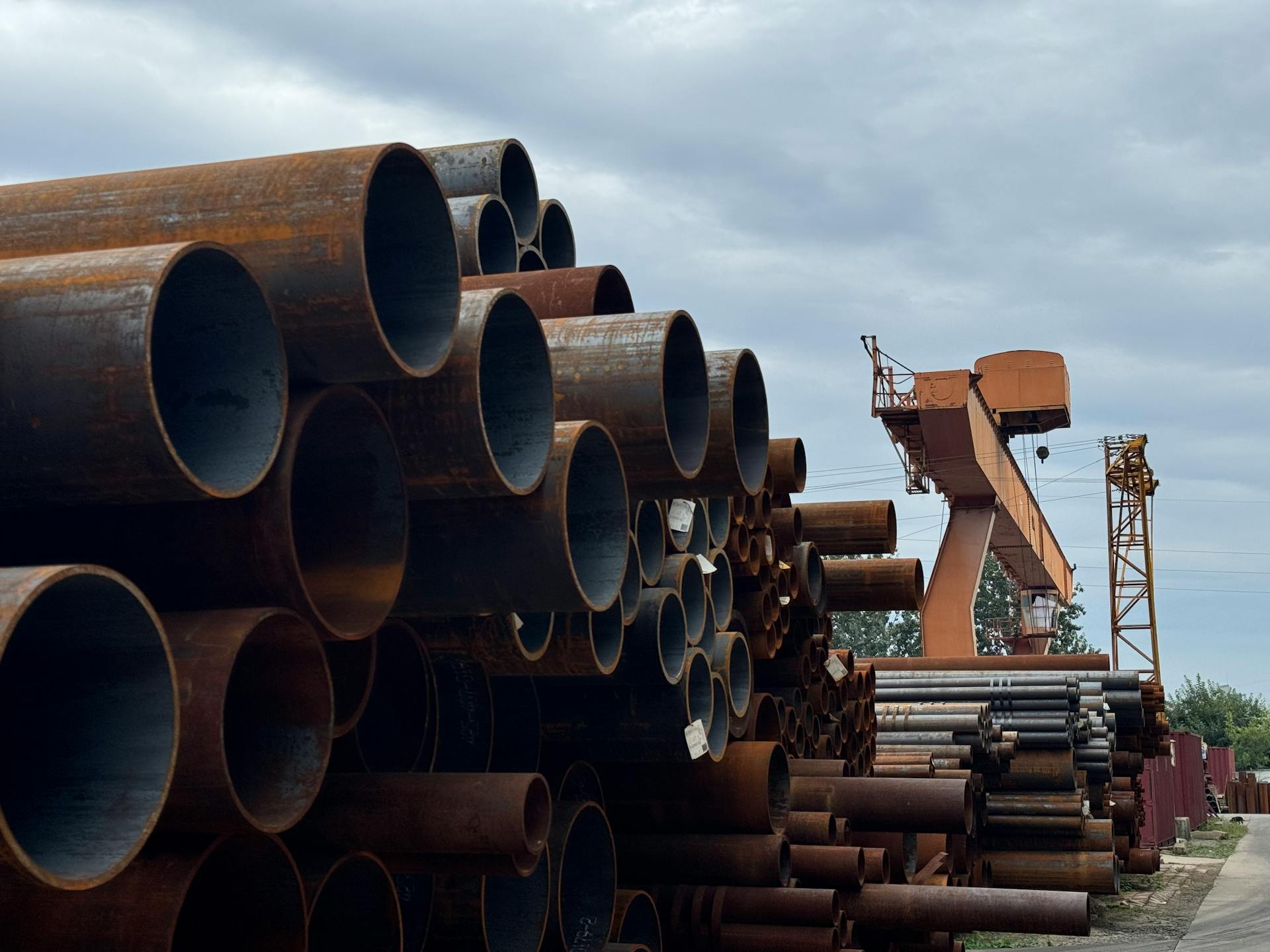
Pipe-pile stock at a port-side yard. Diameters above 1000 mm are typically spiral submerged-arc welded (SSAW).
Anatomy of a Steel Pipe Pile
Six components that turn a steel tube into a deep foundation.
A driven steel pipe pile is a layered system: the steel shell carries the driving hammer energy and the structural load, an internal reinforced concrete plug transfers that load to the steel via composite action, and an external coating shields the shell from soil-side corrosion. The tip carries a hard-faced shoe to break through dense layers, and segments are joined at the surface with backing-ring butt welds as the pile is driven deeper.
Pile shoe (driving tip)
Cast-steel or fabricated conical point welded to the bottom segment. Hard-faced for boulder-bearing strata. Optional H-beam or flat plate variants for soft over dense soil profiles.
- Shoe details
- • Cast steel ASTM A27 / fabricated
- • Hard-facing: ER wear plate optional
- • Welded with matching-strength electrode
Splice / backing ring
Butt-weld connection between segments as the pile is driven deeper. Backing ring ensures 100% root fusion; weld is 100% UT (AWS D1.1).
- Field splice
- • AWS D1.1 full-penetration groove
- • Backing ring ASTM A36 / S355
- • 100% UT after weld, before re-drive
Internal concrete & rebar
Fills the upper length to develop composite action. Rebar cage extends from the pile cap down into the plug; tremie placement for water-bearing strata.
- Composite action
- • Concrete ≥ C30 / 35 MPa typical
- • Rebar ASTM A615 Gr.60 / B500B
- • Plug length designed for load transfer
Pile cap & coating
Reinforced concrete cap distributes column load to the pile group. Below grade, 3LPE / FBE / bitumen coating + CP protects the shell; splash zone often uses extra wrap or HDPE sleeve.
- Top & underground
- • 3LPE per ISO 21809-1 / DIN 30670
- • FBE per AWWA C213 / CSA Z245.20
- • CP per EN 12696 / NACE SP0169
Six Service Environments, Six Different Spec Sheets
Pick the parameter that drives selection for each job.
The same pipe pile family serves very different ground conditions, water depths, and design codes. Below are the six service environments we see most often — each pushes a different parameter to the front: driveability, fatigue, splash-zone corrosion, or composite action with the internal concrete.
Bridges & elevated highways
Driven pipe pile bents for piers and abutments where the cap is at or above the waterline. Common diameters 600–1500 mm, lengths 20–60 m.
- Key specifications
- • AASHTO LRFD Bridge §10
- • ASTM A252 Gr.2/3, EN 10219 S355J2H
- • Driving: diesel / hydraulic hammer
- • Splice-welded in the leads
Port, jetty & wharf structures
Mooring dolphins, breasting dolphins, crane-beam pile caps in aggressive marine / splash-zone conditions. Heavy wall + dual coating + cathodic protection standard.
- Key specifications
- • Up to 50 mm wall for abrasion
- • 3LPE + glass flake + sacrificial anodes
- • EN 1993-5 / BS 6349 maritime
High-rise tower foundations
Large-diameter bored or driven pipe piles, often filled with high-strength concrete + rebar to develop composite section capacity.
- Key specifications
- • OD 1000–2500 mm, L up to 90 m
- • Internal C40–C60 concrete + rebar cage
- • Static load test on sacrificial pile
Solar tracker / PV mounting
Smaller-diameter driven piles (114–219 mm) rammed into the ground by the tracker’s own post-pounder. Light wall, hot-dip galvanized, fast production cycle.
- Key specifications
- • EN 10219 S235JRH / S275J0H
- • Wall 3.6–6.0 mm typical
- • HDG per ISO 1461 / ASTM A123
Retaining & cofferdam walls
Pipe piles in a secant or tangent wall carry cantilever or propped lateral loads; stiffness dominates selection. Higher grade often chosen to reduce tonnage.
- Key specifications
- • EN 1993-5 / EN 1997
- • L 12–25 m common
- • A252 Gr.3 / S355J2H / API 5L X52
Offshore wind monopiles
Single large-diameter transition piece foundation, typically 5–10 MW turbines. Heavy wall, tight dimensional tolerances, fatigue-driven design.
- Key specifications
- • OD 6–10 m, wall 60–110 mm
- • S355ML / S420ML per EN 10025-4
- • EN 1090-2 EXC3/4 execution class
Steel Grades & Wall Thickness
The grade sets the strength, the strength sets the driving stress, and the driving stress sets the minimum wall.
A pipe pile is only as good as the steel behind it. Yield strength sets the allowable driving stress (typically 0.9 Fy per AASHTO §10.7.3) and therefore the minimum wall for a given load; tensile strength sets the splice-weld matching requirements; impact and elongation cover cold-climate and seismic zones. Wall thickness itself balances three forces — driving stress, corrosion allowance (1–5 mm by environment and design life) and handling stiffness.
Grade comparison table
ASTM A252 vs JIS A 5525 / A 5530 vs EN 10219 vs API 5L
| Grade | Fy min (MPa) | Fu (MPa) | Elong. | Notes |
|---|---|---|---|---|
| ASTM A252 Gr.1 | 205 | 345 | 30% (2 in) | Welded & seamless pipe piles |
| ASTM A252 Gr.2 | 240 | 415 | 25% (2 in) | Higher-load piling |
| ASTM A252 Gr.3 | 310 | 455 | 20% (2 in) | Heavy-duty, axial + lateral |
| JIS A 5525 SKK400 | 235 | 400 | 18% (5号) | Japan domestic piling |
| JIS A 5525 SKK490 | 315 | 490 | 18% (5号) | Japan domestic heavy piling |
| JIS A 5530 SKY400/490 | 235/315 | 400/490 | 18% | Steel pipe sheet piles |
| EN 10219 S275J0H | 275 | 410–560 | 20% | Cold-formed structural hollow |
| EN 10219 S355J2H | 355 | 470–630 | 20% | Cold-formed, -20 °C impact |
| EN 10219 S355K2H | 355 | 470–630 | 20% | Cold-formed, 27J @ -30 °C |
| API 5L X52 PSL1 / PSL2 | 360 | 460 / 760 | Per spec | Line pipe repurposed for piling |
| API 5L X65 PSL1 / PSL2 | 450 | 535–760 | Per spec | High-strength tubular pile |
Wall-thickness quick reference
610 mm OD, L = 30 m, axial load 5,000 kN, 0.9 Fy driving-stress basis
| Grade | Fy (MPa) | Allowable 0.9 Fy (MPa) | Min. wall for 5,000 kN @ 610 mm OD | Steel saving vs Gr.1 |
|---|---|---|---|---|
| ASTM A252 Gr.1 | 205 | 184.5 | 14.5 mm | — |
| ASTM A252 Gr.2 | 240 | 216.0 | 12.3 mm | −15 % |
| ASTM A252 Gr.3 | 310 | 279.0 | 9.5 mm | −34 % |
| JIS A 5525 SKK400 | 235 | 211.5 | 12.6 mm | −13 % |
| JIS A 5525 SKK490 | 315 | 283.5 | 9.4 mm | −35 % |
| EN 10219 S275J0H | 275 | 247.5 | 10.7 mm | −26 % |
| EN 10219 S355J2H | 355 | 319.5 | 8.3 mm | −42 % |
| API 5L X52 PSL1 / PSL2 | 360 | 324.0 | 8.2 mm | −43 % |
| API 5L X65 PSL1 / PSL2 | 450 | 405.0 | 6.5 mm | −55 % |
| API 5L X80 PSL2 | 555 | 499.5 | 5.3 mm † | −63 % |
Indicative sizing for 610 mm OD under a 5,000 kN axial load: the wall is the steel area at which the load reaches the 0.9 Fy driving-stress limit. Corrosion allowance and handling minimum are excluded — apply the code resistance factor before using it as a design capacity. † At high grades the stress limit stops governing: practical minimum wall for handling and manufacture (typ. ≥ 8 mm at this diameter) takes over, so X65 / X80 pay off through lower tonnage and fewer splice welds rather than through ever-thinner walls.
Chemical Composition & Weldability
Yield strength is what the pile carries; carbon equivalent is what the splice has to survive.
Pipe piles are low-carbon steels, so the strength comes from manganese and micro-alloying rather than from carbon. What decides the site work is the carbon equivalent: it sets the preheat temperature, the risk of hydrogen cracking in the girth weld, and how the heat-affected zone behaves next to a 100 %-penetration splice. ASTM A252 does not cap it — if the splice matters, put a CEV or Pcm limit on the enquiry.
Chemical composition — ladle analysis, % max
ASTM A252 sets mechanical properties and leaves the chemistry open; EN 10219 and API 5L PSL2 cap it.
| Steel / grade | C max | Si max | Mn max | P max | S max | CEV max |
|---|---|---|---|---|---|---|
| ASTM A252 Gr.1 / 2 / 3 | 0.26 | 0.45 | 1.60 | 0.050 | 0.030 | Not specified |
| EN 10219 S275J0H | 0.20 | — | 1.50 | 0.035 | 0.035 | 0.40 |
| EN 10219 S355J2H | 0.22 | 0.55 | 1.60 | 0.030 | 0.030 | 0.45 |
| API 5L X52 PSL2 | 0.22 | — | 1.40 | 0.025 | 0.015 | 0.43 / Pcm 0.25 |
| API 5L X65 PSL2 | 0.22 | — | 1.45 | 0.025 | 0.015 | 0.43 / Pcm 0.25 |
| API 5L X80 PSL2 | 0.22 | — | 1.90 | 0.025 | 0.015 | 0.43 / Pcm 0.25 |
What the chemistry does to the field splice
Carbon equivalent — not yield strength — decides whether the girth weld can be made cold.
| Weldability driver | Limit / value | Consequence for the splice |
|---|---|---|
| CEV (IIW) ≤ 0.43 | EN 10219 / API 5L PSL2 | No mandatory preheat for wall ≤ 25 mm at ≥ 10 °C ambient |
| CEV > 0.43, or wall > 25 mm | EN 1011-2 | Preheat 100–150 °C and confirm with a hardness survey |
| Pcm ≤ 0.25 | API 5L PSL2 | Low heat-affected-zone hardening — most tolerant of fast field welding |
| C ≤ 0.26 | ASTM A252 | No carbon-equivalent clause: specify CEV / Pcm yourself when the splice is critical |
| S ≤ 0.015 | API 5L PSL2 | Limits hot-cracking risk in the weld pool |
| Hydrogen | E70XX-H4 or E81T1, heated quiver | Re-bake electrodes per the manufacturer — damp consumables are the main cause of delayed cracking |
How a Pipe Pile Carries Its Load
Qu = Qs + Qb — and the two halves mobilise at very different settlements.
Ultimate axial capacity is the sum of shaft resistance and base resistance. Because shaft friction is fully mobilised within millimetres while base resistance needs tens of millimetres, the two are conservatively added in design — and a load test that stops at working load never sees the full capacity the pile will carry. The parameters below are the ones we use to sanity-check a pile section before the geotechnical report arrives.
Unit skin friction and end bearing — cohesionless soil
Indicative design parameters per API RP 2A / ISO 19902. Project-specific geotechnical data governs.
| Soil condition | Interface friction angle δ | Max. unit skin friction f (kPa) | Bearing factor Nq | Max. unit end bearing q (MPa) |
|---|---|---|---|---|
| Very loose / loose sand, silt | 15° | 47.8 | 8 | 1.9 |
| Loose to medium-dense sand | 20° | 67.0 | 12 | 2.9 |
| Medium-dense sand | 25° | 81.3 | 20 | 4.8 |
| Dense to very dense sand | 30° | 95.7 | 40 | 9.6 |
| Dense to very dense gravelly sand | 35° | 114.8 | 50 | 12.0 |
Clay — the α method
Shaft friction is f = α × cu, with α = 0.5 ψ−0.5 for ψ = cu / p′ ≤ 1.0 and α = 0.5 ψ−0.25 above that, capped at α ≤ 1.0. End bearing is q = 9 cu.
- Key specifications
- • Take the lower of plugged and unplugged
- • Undrained shear strength cu governs both terms
- • For long piles the residual shaft friction governs
Plugged or unplugged?
An open-ended pipe is checked twice and the lower result governs: unplugged — external plus internal shaft friction and bearing on the annulus only; plugged — external shaft friction plus bearing on the full section.
- Key specifications
- • A pile may drive unplugged and act plugged under load
- • The soil plug often out-performs the annulus
- • Under scour, do not rely on the internal plug
Why the two terms do not peak together
Shaft friction is essentially fully mobilised at 5–10 mm of head movement. Full end bearing needs 5–10 % of the diameter — 50–100 mm on a 1000 mm pile.
- Key specifications
- • Static load tests must run well past working load
- • PDA restrikes are read after re-consolidation
- • Design assumes both are fully mobilised — conservative
Manufacturing Routes for Pipe Piles
Four processes, one job spec — choose by diameter, wall, cost.
Four processes — SMLS, ERW, LSAW and SSAW — between them cover the entire piling diameter range. The selection is usually driven by the diameter and wall combination, with cost, lead time and welding-seam inspection rules as the secondary filters.
Process comparison
Each process has a sweet spot — match it to the project diameter
| Process | Typical OD | Wall | Joint | Where it fits |
|---|---|---|---|---|
| Seamless (SMLS) | 60–660 mm | 6–80 mm | Single length, no weld | High-pressure piles, thick walls, small batches |
| ERW / HFW | 60–610 mm | 3.6–16 mm | Straight seam, flash-welded | Solar tracker piles, light structural piles |
| LSAW (UOE/JCOE) | 406–1422 mm | 6–40 mm | Straight seam, double-submerged-arc | Bridge piers, port structures, large-diameter piling |
| SSAW (spiral) | 219–2540 mm | 6–25 mm | Helical seam, double-submerged-arc | Offshore wind monopiles, large-port projects, wharf dolphins |
Splices & Pile Shoes
Two custom fabrications that turn pipe segments into a driven pile.
Field splicing and the pile shoe are the two custom fabrications that make a driven pipe pile work. The splice is a full-penetration butt weld with a backing ring, done in the leads after the previous segment is driven. The shoe is a cast-steel or fabricated point welded to the bottom segment, hard-faced for boulder-bearing strata.
Field splice specification
Butt-welded pile splice — the values a WPS has to carry before the pile goes into the leads.
| Item | Specification | Reference |
|---|---|---|
| Joint type | Full-penetration single-V butt weld with a steel backing ring, welded in the leads | AWS D1.1 prequalified |
| Bevel / included angle | Single-V 60°–75° total; 30°–37.5° per side, root face 1.5–3 mm | AWS D1.1 Fig. 3.3 |
| Root gap | 2–4 mm with backing ring; ring tacked at 4 points before welding | Fit-up practice |
| Hi-lo (offset) | ≤ 3 mm (1/8 in) between mating bores | AWS D1.1 Table 3.3 |
| Electrode | E70XX low-hydrogen, or E81T1 flux-cored matching base metal; dry, heated quiver | AWS A5.1 / A5.20 |
| Preheat | ≥ 10 °C ambient minimum; 100–150 °C when CEV > 0.43 or wall > 25 mm | EN 1011-2 |
| NDT | 100 % ultrasonic after cool-down (min. 8 h for thick wall), before the next segment is set | AWS D1.1 / EN ISO 17640 |
| Splice position | Keep above the mudline where possible so the weld stays inspectable and re-drivable | Execution practice |
Closed conical shoe
Cast-steel or fabricated cone welded to the bottom segment. Breaks through boulders and dense layers and protects the shell end from brooming. Optional hard-facing weld overlay on the tip.
- Key specifications
- • Cast steel ASTM A27 Gr.60-30 / fabricated
- • Hard-facing overlay for rock and boulder strata
- • Shoe wall ≥ pile wall, full-penetration weld
H-beam / cross-plate shoe
Plate or H-section tip for a soft layer sitting on dense ground or sloping rock. The plate cuts a seat so the pile does not deflect off the bearing stratum.
- Key specifications
- • A36 / S355 plate, thickness ≥ pile wall
- • Used with pre-boring or jetting if required
- • Also protects against ovalisation on refusal
Open-ended (no shoe)
Plain pipe end. Soil enters the tube and forms a plug that is often stronger than the surrounding soil — this is the standard, most economical configuration for friction piles.
- Key specifications
- • Soil plug transfers load by composite action
- • No tip fabrication cost, fastest delivery
- • Check plugged vs unplugged capacity (see load-transfer section)
Driveability, Hammer Selection & Integrity Testing
Predict before you drive, then prove after you drive.
A pile that cannot be driven to the design depth is a site problem that no steel grade will fix. A wave-equation driveability study predicts the driving stress, the blow count at the end of drive and the hammer energy required, so the shell is neither under-driven nor over-stressed — it is the cheapest piece of engineering on a piling project. After driving, dynamic and static tests confirm the capacity the analysis predicted.
Driving-stress and hammer rules
The numbers that turn a pile section into a driving plan.
| Parameter | Typical rule | Basis |
|---|---|---|
| Max. driving stress (compression) | 0.90 × Fy | AASHTO LRFD §10.7.8 — also written into state DOT specifications |
| Hammer rated energy | ≥ 15 % of the design ultimate capacity (ft·lb vs lb) | MaineDOT geotechnical practice |
| Refusal criteria | Stop at about 5 blows per 6 mm (1/4 in); cap 120 blows per 300 mm | WYDOT / MaineDOT piling specifications |
| Restrike | 24 h after end of drive, before acceptance | PDA / CAPWAP practice — pore pressure needs to dissipate |
| Pile cushion | 75–150 mm plywood or micarta; replace every 50–100 piles | Protects the pile head and the hammer |
| Tensile stress during driving | Keep below roughly 0.45–0.5 Fy | Wave-equation output, avoids head cracking |
| Splice level | Keep above the mudline where possible | Weld inspection and re-drive access |
Test methods & standards
PDA + CAPWAP on 5–10% of piles; static load on sacrificial piles
| Test | Standard | What it tells you | When to use |
|---|---|---|---|
| High-strain dynamic (PDA) | ASTM D4945 | Bearing capacity, driving stress, hammer efficiency | Every project, 5–10% of piles |
| CAPWAP signal matching | Pile Dynamics | Static capacity from PDA data | Following every PDA test |
| GRLWEAP wave equation analysis | Pile Dynamics | Hammer selection, driveability, set per blow | Pre-construction |
| Static axial compression load | ASTM D1143 | True axial capacity, Q-s curve | 1–2 sacrificial piles per site |
| Static axial tension load | ASTM D3689 | Uplift / tension capacity | Tension piles, anchor piles |
| Static lateral load | ASTM D3966 | Lateral capacity, p-y curve | Heavily loaded lateral piles |
| Low-strain integrity (sonic echo) | ASTM D5882 | Pile length & major defects | 100% QC, post-install |
| Crosshole sonic logging (CSL) | ASTM D6760 | Internal concrete defects | Bored piles with rebar cage |
| Pile integrity (PIT) | ASTM D5882-16 | Quick integrity screen | Driven concrete-filled piles |
Hammer & cushion sizing
Required rated energy, ram weight and cushion stiffness for the selected pile, the chosen hammer and the actual soil profile — not a catalogue rule of thumb.
- Key specifications
- • One run per soil profile and pile size
- • Penetration rate predicted per blow
- • Equipment sized before the plant is mobilised
Stress envelope at every depth
Maximum compressive and tensile stress along the pile during driving, checked against 0.9 Fy and roughly 0.45–0.5 Fy respectively, so a hard layer cannot quietly overstress the shell.
- Key specifications
- • Compression checked against 0.9 Fy
- • Tension checked against head-cracking limits
- • Flags the depth where refusal becomes overstress
Blow count and set
Predicted blows per 250 mm against depth. The site compares actual set with the predicted curve, so refusal and acceptance are called on data rather than on feel.
- Key specifications
- • Driving criteria issued before piling starts
- • Deviation triggers a restrike, not a guess
- • Feeds directly into the PDA acceptance plan
Corrosion, Coatings & Cathodic Protection
Splash zone is the weakest link; design the rest of the pile to last as long.
Buried steel pipe piles last 50–100+ years if the corrosion allowance and the coating are specified correctly. The splash-and-tidal zone is the most aggressive and is almost always over-coated with HDPE sleeve or a polyurethane jacket. Below the waterline, sacrificial anodes (Al or Zn) or impressed-current systems (per NACE SP0169 / EN 12696) carry the protection.
Designers typically add a 1 mm corrosion allowance for atmospheric service, 2 mm for splash / buried fresh water, and 3–5 mm for marine splash and buried saltwater zones — and they cover the design life (commonly 50 or 100 years) in the specification.
Corrosion rate & protection by zone
Indicative rates for unprotected carbon steel — coating + CP add decades
| Environment | Corrosion rate (mm/yr) | Coating system | CP? |
|---|---|---|---|
| Atmospheric (rural) | 0.01–0.05 | None / paint per ISO 12944 C2 | No |
| Atmospheric (marine) | 0.05–0.15 | Epoxy / PU per ISO 12944 C5-M | No |
| Splash & tidal zone | 0.30–0.60 | 3LPE + HDPE sleeve / J-tube wrap | Yes |
| Buried (soil, undisturbed) | 0.01–0.03 | 3LPE / FBE / bitumen | Yes (sacrificial) |
| Buried (aggressive soil) | 0.05–0.20 | 3LPE + CP | Yes (impressed current) |
| Submerged (seawater) | 0.10–0.30 | 3LPE + CP | Yes (Al / Zn anodes) |
Design Codes & Material Standards
Pick the design code first, the material standard second.
Pile design is governed by a stack of codes: structural steel code, geotechnical code and the project-specific execution class. Underneath them sits the material standard — and A252, API 5L and EN 10219 are not interchangeable. They differ mainly in how strictly they control weld integrity, testing and tolerances, which is exactly where the price gap comes from.
Common code stacks
Pick the design code first, the material standard second
| Code | Scope | Where it applies |
|---|---|---|
| AASHTO LRFD Bridge Design Spec. §10 | Pile foundation design, driving stress 0.9 Fy, structural resistance | US highway & bridge projects |
| AASHTO M 270 / ASTM A709 | Bridge steel plate (referenced by AASHTO for pile splices) | Splice backing rings |
| EN 1993-5 (Eurocode 3 Part 5) | Piling — design of steel bearing piles | EU piling, both driven & bored |
| EN 1997-1 | Geotechnical design — pile actions, ULS / SLS | EU piling, geotechnical interface |
| EN 1090-2 EXC3 / EXC4 | Execution class for fabrication & welding | Offshore & critical piles |
| API RP 2A-WSD / ISO 19902 | Fixed offshore steel structures, pile design & fatigue | Offshore platforms, subsea piles |
| AISC 360 / AISC Steel Construction Manual | Steel building piles, column-base piles | US high-rise & industrial |
| JIS A 5525 / JIS A 5530 | Steel pipe piles / sheet piles (Japan domestic) | Japan piling market |
| BS 6349 / BS 8004 | Maritime & earth-retaining structures | UK port & cofferdam |
Choosing the material standard
ASTM A252 vs API 5L PSL2 vs EN 10219 — where the price gap comes from
| Standard | Scope | Key requirements | Typical use |
|---|---|---|---|
| ASTM A252 Gr.2 / Gr.3 | Welded or seamless pipe piles | Min yield 240 / 310 MPa (35 / 45 ksi); no hydrostatic test required by design | Land piling, friction piles, CAS casings |
| API 5L PSL1 / PSL2 | Line pipe used as piles | Full hydrostatic test; PSL2 adds weld-seam NDE and toughness requirements; tighter tolerances | Marine piles, high-strain driving, CAS where integrity is critical |
| EN 10219 S275J0H / S355J2H | Cold-formed structural hollow sections | Impact classes J0 / J2; tight section tolerances | Combined walls, visible piles, low-vibration installation |
Note: A252 deliberately omits hydrostatic testing because piles do not retain pressure — that omission is intentional, not a quality gap. When a marine drive or hard refusal punishes the seam, upgrading to API 5L PSL2 buys you a tested weld.
Tolerances, Testing & Quality Assurance
The tolerance line is often the real difference between two otherwise equal quotes.
Two mills can quote the same diameter, wall and grade and still ship a different product — this is where ASTM A252, EN 10219 and API 5L PSL2 genuinely diverge. The table sets the requirements side by side; the cards below show what we test on every heat, and how each test ties back to a clause in the spec.
Tolerance and test requirements, side by side
Same diameter, same wall, same grade — and still a different product.
| Requirement | ASTM A252 | EN 10219-1 / -2 | API 5L PSL2 |
|---|---|---|---|
| Outside diameter | ±1 % of specified OD | ±1 % (EN 10219-2) | Per API 5L tables |
| Wall thickness | −12.5 % of nominal, no plus limit | Per EN 10219-2 (typ. ±10 %) | −12.5 % typical, process-dependent |
| Unit weight | +15 % / −5 % | — | — |
| Hydrostatic test | Not required | Not required | 100 % of pipe |
| Charpy impact | Not required | 27 J at 0 °C (J0); −20 °C (J2) | 27 J at 0 °C typical, transverse / longitudinal |
| Weld-seam NDT | Not mandated | Not mandated | 100 % on PSL2 |
| Inspection document | MTC, per heat, heat-traceable | EN 10204 3.1 | EN 10204 3.1 |
Why the tolerance line moves the price
A252 deliberately omits hydrostatic testing: a pile is not a pressure vessel, and the omission is intentional rather than a quality gap. What you buy with EN 10219 and API 5L PSL2 is tighter dimensional control, mandatory toughness and 100 % weld-seam inspection — worth paying for when the pile is spliced every 12 m in the leads, threaded into a drive tip, or seated on a template in a cofferdam.
Dimensional
OD ±1%, wall -12.5% (A252), straightness 0.1% L, end squareness ±2 mm
- Key specifications
- • Per ASTM A252 §12 / EN 10219 §6.7 / JIS A 5525
Chemical
Heat & product analysis: C, Mn, S, P, CEV where specified
- Key specifications
- • ASTM A751 / EN 10219-1 Table A.1 / JIS G 0404
Tensile
Yield, tensile, elongation on transverse or longitudinal specimens
- Key specifications
- • ASTM A370 / EN ISO 6892-1 / JIS Z 2241
Impact (Charpy V)
27 J minimum, J0 @ 0 °C, J2 @ -20 °C, K2 @ -30 °C where specified
- Key specifications
- • EN 10219-1 §6.7 / ASTM A370 §16 / JIS Z 2242
NDT on weld seam
100% UT or RT on LSAW / SSAW seam, AWS D1.1 acceptance
- Key specifications
- • AWS D1.1 / EN ISO 17640 / EN 10219 §6.7.3
Hydrostatic test
Required by API 5L when line pipe is repurposed; optional per A252
- Key specifications
- • ASTM A252 §17 (as applicable) / API 5L §10.3
Visual & marking
Heat number, grade, OD × wall × length, ASTM/JIS/EN stamp
- Key specifications
- • ASTM A252 §22 / EN 10219 §10 / JIS A 5525 §6
Weights, Logistics & Handling
Kilogrammes per metre decide the crane, the truck and the freight.
Weight per metre follows directly from the nominal wall, and everything downstream follows from the weight: lifting points, sling angle, the crane’s rated capacity at radius, the truck axle loading and the freight bracket. Getting the number wrong at enquiry stage is how a pile that is correct on paper becomes expensive on site.
Weight per metre and per 30 m pile
W = 0.02466 × t × (D − t) kg/m, for steel at 7,850 kg/m³.
| OD (mm) | Wall (mm) | kg/m | 30 m pile (t) | Typical route |
|---|---|---|---|---|
| 406.4 | 9.5 | 93.0 | 2.79 | ERW / seamless |
| 508 | 12.7 | 155.1 | 4.65 | ERW / LSAW |
| 610 | 12.7 | 187.1 | 5.61 | SSAW / LSAW |
| 610 | 19.1 | 278.3 | 8.35 | SSAW / seamless |
| 762 | 12.7 | 234.7 | 7.04 | SSAW |
| 914 | 19.1 | 421.5 | 12.65 | SSAW / LSAW |
| 1016 | 25.4 | 620.5 | 18.61 | SSAW / LSAW |
| 1219 | 25.4 | 747.6 | 22.43 | SSAW / LSAW |
Stacking & yard
Timber skids clear of standing water, chocks to stop the stack rolling, bevels kept clean and coated zones wrapped before they go into the stack.
- Key specifications
- • Never stack on bare ground
- • Protect bevels — a damaged bevel costs a weld
- • Coated zones wrapped during stacking
Slings & ovality
Two wide spreader slings rather than a single-point pick. A 30 m, 1219 × 25.4 mm pile is over 22 t before slings and shackles, and a single-point pick is how piles arrive out of round.
- Key specifications
- • Check ovality after any rough handling
- • Lift weight = kg/m × length
- • Add sling and shackle weight to the crane chart
Lengths & splices
Coil or plate route drives mill lead time. 30 m piles normally ship as 12 m or 24 m sections and are spliced on site — so the splice count in the quotation is a freight decision as much as a welding one.
- Key specifications
- • Longer sections: fewer welds, higher freight
- • Confirm max. transport length before quoting
- • Splice count feeds the welding and NDT cost
A Six-Step Decision Guide
From loads and codes to splice and coating — the spec the mill needs.
Define the loads & codes
Axial, lateral, moment, and which code stack applies. AASHTO, EN 1993-5, API 2A or JIS A 5525 each set different default factors.
Pick the diameter
From the column / cap layout and the in-service stiffness required. OD typically 200–2500 mm; small OD for solar, large for offshore wind.
Choose the grade
Fy drives the allowable driving stress. Use Gr.1 for light loads, Gr.3 / SKK490 / S355J2H / X52 for medium, X65 / X80 for heavy axial.
Calculate wall thickness
From driving stress (0.9 Fy), corrosion allowance, and handling stiffness. Add 12.5% to wall for ASTM A252 negative tolerance.
Pick the manufacturing route
SMLS for thick / pressure-bearing, ERW for small solar piles, LSAW for mid-diameter bridge piers, SSAW for very large monopiles.
Specify splicing, shoe & coating
Backing-ring butt welds per AWS D1.1, hard-faced cast-steel shoe for dense soils, 3LPE / FBE + CP for the corrosion zones.
Standards & Certification Map
A complete pipe-pile specification is a stack of 25+ standards — from the product spec through design, welding, testing, coating and cathodic protection. The five columns on this page are the ones our mill & engineering team reach for first; project-specific clauses (fatigue, seismic, AEX, sour service) are added on top.
Product standards
- ASTM A252 / A252M — Gr.1 / Gr.2 / Gr.3 — welded and seamless steel pipe piles
- JIS A 5525 — Steel pipe piles — SKK400, SKK490
- JIS A 5530 — Steel pipe sheet piles — SKY400, SKY490
- EN 10219-1 / -2 — Cold-formed welded structural hollow sections
- EN 10210-1 / -2 — Hot-finished structural hollow sections
- API 5L PSL1 / PSL2 — Line pipe repurposed for piling (X42–X80)
- ASTM A500 — Round HSS — small-diameter structural piles
Material standards
- EN 10025-2 — S235 / S275 / S355 structural steels (parent plate for hollow)
- EN 10025-4 — S355M / S420M / S460M thermomechanical for offshore monopiles
- ASTM A36 / A572 — Splice backing rings, cap plates
- ASTM A615 / A706 — Reinforcing steel for the internal concrete plug
Testing & NDT
- ASTM D4945 — High-strain dynamic testing of deep foundations
- ASTM D1143 / D3689 / D3966 — Static axial / tension / lateral load tests
- ASTM D5882 — Low-strain integrity testing
- ASTM D6760 — Crosshole sonic logging of bored piles
- AWS D1.1 — Structural welding — splices & shoes
- EN 10204 3.1 / 3.2 — Mill test certificate
- ISO 9001 / ISO 3834-2 — Quality system & welding qualification
Design & execution
- AASHTO LRFD Bridge §10 — US bridge pile design
- EN 1993-5 (Eurocode 3-5) — Piling — design of steel piles
- EN 1997-1 — Geotechnical design
- EN 1090-2 EXC2/3/4 — Execution class for fabrication
- API RP 2A-WSD / ISO 19902 — Offshore fixed structures
- JIS A 5525 / JIS A 5530 — Japan domestic piling design basis
- AISC 360 — US steel building piles
Coatings & CP
- ISO 21809-1 — 3LPE external coating for buried / submerged service
- DIN 30670 — 3LPE — European implementation reference
- AWWA C213 / CSA Z245.20 — FBE coating
- ISO 12944 — Atmospheric paint systems for above-grade
- NACE SP0169 / EN 12696 — Cathodic protection of buried / submerged
Frequently Asked Questions
Twelve questions we hear most often from pile buyers, contractors and design engineers.
What wall thickness should I specify for a 600 mm OD, 30 m long A252 Gr.2 pile?
For 610 mm OD / 30 m long / 5000 kN axial, 9.5–12.7 mm is the typical envelope. Final wall must satisfy 0.9 Fy driving stress, the negative tolerance (-12.5% per A252), and the corrosion allowance (1–2 mm for buried / 3 mm for marine splash).
Can I use API 5L line pipe as a pipe pile?
Yes, and it is common practice for large-diameter piling where line-pipe supply chains are deeper. Specify X42–X65 per API 5L PSL1 or PSL2 (PSL2 mandatory for fatigue / sour service), then refer to AASHTO §10 / EN 1993-5 for the driving-stress and structural checks.
What is the allowable driving stress for a steel pipe pile?
AASHTO LRFD Bridge §10 uses 0.9 × Fy as the effective driving stress. EN 1993-5 imposes a similar cap on combined stress during driving. Both can be relaxed if a wave-equation analysis (GRLWEAP) and PDA test confirm a milder driving.
Do I need a pile shoe for soft over dense soil?
Usually yes — a hard-faced conical or H-beam shoe protects the bottom of the pipe from brooming or splitting when it punches through the dense layer. The shoe is welded on at the lay-down yard before the first segment goes into the leads.
How do I field-splice two segments without losing driving energy?
Butt-weld with a backing ring, full-penetration groove, matching-strength electrode. The weld is 100% UT after cool-down, before the next segment is set on top. AWS D1.1 is the usual reference; some port projects require 100% RT on every splice.
What coating system should I use for a marine pile?
Three-layer polyethylene (3LPE) per ISO 21809-1 / DIN 30670 from the mudline down to the pile tip, plus a separate HDPE sleeve or polyurethane wrap in the splash & tidal zone. Above the splash zone, an ISO 12944 C5-M paint system. Couple with Al / Zn sacrificial anodes per NACE SP0169 / EN 12696.
Is low-strain integrity testing enough for QA?
For 100% screening of every driven pile, yes — ASTM D5882 detects major defects, necking, and missing length. Pair it with PDA (ASTM D4945) on 5–10% of piles and a static load test (ASTM D1143) on one or two sacrificial piles for the design confirmation.
What is PDA testing and when is it worthwhile?
The Pile Driving Analyzer measures force and velocity at the pile head during every blow, giving driving-stress verification and a capacity estimate under high-strain dynamic testing (ASTM D4945). It is standard practice on marine and large land projects; pair it with CAPWAP signal matching and restrikes for calibrated capacity.
How should piles be stored and handled before driving?
Store on timber skids clear of standing water, keep bevels clean, lift with wide spreader slings rather than single-point picks to avoid ovality, and wrap any coated zones during stacking. Ovality and bevel damage cost far more at the hammer than they do in the yard.
How do I decide between an open-ended and a closed-ended pile?
Open-ended is the default: the soil plug that forms inside adds capacity and driving resistance stays lower. Check both conditions — unplugged (external and internal shaft friction, bearing on the annulus) and plugged (external shaft friction, bearing on the full section) — and design for the lower value. A closed or shoe-fitted end is chosen when the tip has to punch through a dense layer, when the pile is seated on rock, or where the internal plug cannot be relied on, such as in a scour zone.
How much corrosion allowance should I add for a 50-year design life?
Use the exposure rates on this page as the starting point: roughly 0.01–0.03 mm/yr buried, 0.10–0.30 mm/yr submerged and 0.30–0.60 mm/yr in the splash zone. Over 50 years that is 0.5–1.5 mm buried but 15–30 mm in the splash zone — which is why the splash zone is solved with a coating plus an HDPE sleeve and cathodic protection rather than with extra steel. A common specification adds 1–2 mm for a buried, coated and cathodically protected pile; the calculation basis is EN 1993-5 with ISO 9223 exposure categories.
Do I need pre-boring or jetting in dense sand?
Only when the driveability study says the pile cannot reach the design depth inside the 0.9 Fy driving-stress limit. Pre-boring through the densest layer reduces shaft friction over the drilled length, so it has to be agreed with the geotechnical engineer rather than added on site. Jetting works in granular soil but is restricted in many marine permits because of sediment disturbance. A driving shoe or an H-tip is usually the cheaper first answer.
Why Buyers Choose CREATEEL for Pipe Piles
Mill + splicing + coating + docs, in one supply contract.
Mill-direct pricing
Our pipe mills are SSAW, LSAW, ERW and seamless — we own the production schedule, so quotes are mill-direct, not stockist-rerouted.
Full code coverage
ASTM A252, JIS A 5525 / A 5530, EN 10219, API 5L, EN 1993-5, AASHTO, API RP 2A — single mill for piles that ship to US, EU, Middle East, Southeast Asia, Japan.
Splicing & shoes in-house
We fabricate the pile shoes (cast-steel conical, hard-faced or fabricated) and the backing-ring splices in our own shop, AWS D1.1 qualified welders, 100% UT on every splice weld.
Coating integration
3LPE per ISO 21809-1 / DIN 30670, FBE per AWWA C213, and HDPE sleeve for the splash zone — applied on the same yard as the rolling mill, no double-handling.
Documentation for spec
EN 10204 3.1 mill certificate, third-party 3.2 on request, full traceability of heat number, rolling batch, welding procedure and NDT reports.
Engineering support
Wave-equation analysis (GRLWEAP), splice design per AASHTO §10, and driving-stress review at no extra cost for the first 200 t of each project.
Related CREATEEL Products
Every pipe-pile project is supported by the mill’s wider steel-pipe catalogue.

LSAW Steel Pipe
UOE / JCOE large-diameter pipe 16″–56″ for bridge piers, port structures and large piling.
View product details →
SSAW Steel Pipe
Spiral-submerged-arc welded pipe 219″–2540 mm OD, the workhorse for wharf dolphins and large-port piles.
View product details →
ERW Steel Pipe
Cost-efficient HFW pipe ½″–24″ for solar tracker and small structural piles.
View product details →
Piling Drill Bit
Piling drill bits and tooling matched to the pile diameters we supply — one sourcing interface.
View product details →
3PE Coated Pipe
Three-layer polyethylene coating per ISO 21809-1 / DIN 30670, applied at the mill yard to the same heat.
View product details →
FBE Coated Pipe
Single and dual-layer fusion-bonded epoxy for higher-temperature service and subsea applications.
View product details →Ready to Specify Steel Pipe Piles?
Send us the loads, the diameter, and the project code stack — we will come back with a mill-direct quote, the splice and shoe drawing, and the coating / cathodic protection scope for the design life.
 [email protected] |
  +86 15602135951 |
  WhatsApp Available